

N-type bifacial cell technology, a most efficient electricity cost-effective solution


Introduction
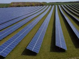
With the increase in the proportion of distributed PV system in the PV market and the promotion of high efficiency single crystalline solar cell technology, more and more institution and enterprises focus on the bifacial structure based on N-type silicon substrate. N-type bifacial cell and module show excellent performance in the regions of highly reflective ground, vertical installation, space station, photovoltaic building integration, parking shed, noise walls, snow, desert and other regions because it’s both side power generation characteristics. Therefore N-type bifacial cell has gradually sought after by the market. According to SEMI international photovoltaic technology roadmap forecast [1], N-type cell market share will be more than 20% to 2019, while it is more than 30% to 2025.
N-type bifacial cell technology
Figure 1a shows the architecture of typical n-type bifacial solar cell in the market. The P+ emitter layer and N+ back surface filed (BSF) layer were form on the front side and rear side of textured n-type substrate, respectively. Passivation layer and anti-reflection layer were form outside both emitter and BSF layer. Silver paste was print on both side and co-firing to form metal electrodes to collect current. Typically, the wafer thickness is around 170-200μm and a wafer resistivity of 1-7Ω·cm is preferred[2,3]. This structure can reach an efficiency of 24.5%[4, 5] in laboratory. Infurther development, the efficiency can reach up to 24.7% by N-PERL and IBC structure [5, 6, 7].

Figure 1, a scheme of n-type bifacial cell structure (left top, 1a), Jolywood’s bifacial cell process flow (right, 1b) and bifacial cells with 4 busbars (left bottom, 1c)
There are several different processes to manufacture such an n-type bifacial cell, such as panda technology from Yingli solar, spin coating based technology from PVGS and so on. Jolywood developed a bifacial cell technology based on ion implantation with the efficiency up to 21.5% at front side (STC) in average and 19% at rear side (STC). As shown in Fig. 1b, the N-type bifacial cell can be implemented by the shown process sequence using an ion implantation technique. This process flow has the advantages of simple process, high yield and high conversion efficiency.

Figure 2, a typical IV cure for front and rear (left, 2a) and a cell efficiency distribution from mass production line with more than 50k cells(right,2b)
A typical IV curve for both front and rear was shown in figure2a, which shows a bifaciality up to 90%. Figure 2b shows a distribution from mass production result with more than 50k cells, demonstrating an average efficiency higher than 21.3% and high yield. Because of the advantages of simple process, high yield, high conversion efficiency, good reliability, easy to upgrade technology, etc., it’s believed in the future N-type market this bifacial technology will be much favored by the market.
Analysis of levelized cost of electricity
Due to the price decrease of the module and material, the module price plays a much smaller role in the PV system cost than several years ago. Thus, levelized cost of electricity (LCOE) analysis is important for end users.
N-type bifacial cells can be assembled in a double glass module or glass-transparent backsheet module according to glass/encapsulate/bifacial cell/encapsulate/glass structure and glass/encapsulate/bifacial cell/encapsulate/transparent backsheet structure, respectively; The transmittance of transparent backsheet is close to 90%, slightly lower than glass. But it has a very light weight Vs. glass. The two kinds of modules can absorb irradiation from both side to generate electrical power, shown in figure 3. Here a PR (performance ratio) factor was used to evaluate the power generation from the backside, which was defined in the following equal (equation 1). This PR factor indicates the ratio of the actual power generation to the theoretical power generation of the nominal power.
(Equation 1)
PVGS Japan have test power generation performance with different double glass module on different reflection ground [8]. In the test, two small systems with same watt-peak were installed on ground with white shell (system A, high reflection ground) and grass(system B, low reflectivity ground) as shown in figure3a and 3b. The measured PR data was shown in table 1. It can be seen that bifacial system has better power generation ration, which is up to 18.7% higher than conventional mono facial system.

Figure 3, glass-glass(or glass-transparent backsheet) module structure(left, 3) and bifacial module test systems(3a: on ground with white shell, 3b: on grass)
Table 1, PR data with different ground condition of different systems
| Bifacial system A | Bifacial system B | Mono facial system | ||
| PR | Max. | 1.16 | 1.08 | 0.93 |
| Avg. | 1.04 | 0.96 | 0.88 | |
| Min. | 0.83 | 0.89 | 0.79 | |
| Electricity generation increase (%) | Max. | 25.7 | 20.3 | Std. |
| Avg. | 18.7 | 10.0 | ||
| Min. | 5.6 | 4.5 |
For the typical south faced PV system with 30° tilt, the electricity generation increase rate can reach up to 26% in sunny days. It can be even high in cloudy days, which can reach up to 38.6%. Detail data was shown in Figure4.

Figure 4,electricity generation increase rate compare with multi system on cement floor (all system is south faced, 30-degree tilt)
Here a rear benefit of 20% was used for calculation. Table 2 shows the different cost per watt by different module based on 100MW PV plant exclude module cost. This indicates that n-type bifacial plant cost exclude module is 25% cheaper than p-type multi plant and 20% lower than p-type mono plant if rear benefit was 20%.
Table 2, 100MW plant calculation with 20% rear benefit, module cost excluded
| Item | P-multi | p-mono | n-mono(20% rear benefit) | Delta | |
| (n-mono)-(p-multi) | (n-mono)-(p-mono) | ||||
| Power(W) | 265 | 280 | 295+59 | / | / |
| Land(kUSD) | 95.3 | 91.0 | 70.9 | -24.4 | -20.1 |
| Rack(kUSD) | 77.8 | 74.3 | 57.9 | -19.9 | -16.4 |
| Cable(kUSD) | 47.6 | 45.5 | 35.5 | -12.2 | -10.0 |
| Infrastructure(kUSD) | 57.2 | 54.6 | 42.6 | -14.6 | -12.0 |
| Installation(kUSD) | 6.4 | 6.1 | 4.7 | -1.6 | -1.3 |
| Sum(kUSD) | 284.3 | 271.4 | 211.6 | -72.7 | -59.8 |
| Sum(USD/W) | 0.28 | 0.27 | 0.21 | -0.07 | -0.06 |
| *all data based on China market | |||||
For different installation, different benefit from rear side also been calculated, list in table 3. This indicates that the n-type system with high power is one of the most cost-effective solution. The system cost will significantly decrease when the system get more benefit from rear side of bifacial modules.
Table 3, system cost calculation with different rear benefit, module cost included
| item | Power | Module price(USD/W) | Plant cost(USD/W) | System cost(USD/W) | LCOE with certain rear benefit(USD/W) | ||||
| 0% | 5% | 10% | 20% | 30% | |||||
| n-mono | 295W | 0.537 | 0.528 | 1.066 | 0.086 | 0.082 | 0.078 | 0.071 | 0.066 |
| p-mono | 280W | 0.478 | 0.542 | 1.019 | 0.090 | ||||
| p-multi | 265W | 0.463 | 0.555 | 1.018 | 0.092 | ||||
| *all data based on China market | |||||||||
Application of N-type bifacial cell and module
N-type bifacial cell and module show excellent performance in the regions of highly reflective ground, vertical installation, space station, photovoltaic building integration, parking shed, noise walls, snow, desert and other regions because it’s both side power generation characteristics. This characteristics greatly expanded the application of N-type bifacial cells and modules[8,9,10].
One of the most important application is vertical installation system. The amount of electricity generated has no correlation with the orientation of the vertical installation. The north-south bifacial vertical installation system shows a parabolic electricity generation during the day, with the peak generation at 12 o’clock, east-west bifacial vertical installation system has two peaks at 9:00 am and 15:00 pm, respectively. The power generation equals 90% of the optimal installation and 130% of the south face vertical installation of mono-facial modules with same watt-peak, shown in figure 5a. Because of the unique advantages of the vertically installed bifacial system, it is ideal for used in soundproof walls on both sides of highways and train stations. Fig 5b shows the first PV soundproof walls installed on the edge of the freeway overpass at Zurich, Switzerland [10].

Figure 5, Left: electricity generation comparison of south-north vertical installation (bifacial: S-N/90°), east-west vertical installation (bifacial: E-W/90°) and optimal south face installation.; Right: the first PV soundproof walls installed on the edge of the freeway overpass at Zurich, Switzerland
The integration of photovoltaic buildings is an important trend in the future development [9,10].In Japan, an architect must take into account the photovoltaic power generation system in the housing design. Double glass modules are undoubtedly the most powerful competitors in this trend. Its characteristics such as double-sided power generation, vertical installation, adjustable light transmittance, good heat dissipation and so on, can been fully exerted in BIPV system.
Figure 6 show some examples of photovoltaic building integration system.

As infrared light cannot be absorbed by silicon, based on bifacial cell structure, most of the infrared light can go through the cell. Furthermore, materials used in bifacial module such as glass, encapsulate and so on do not absorb the infrared light neither. Thus, the heat of the bifacial module is relatively small. The data shows that the glass-glass PV modules have a 5 to 9 lower working temperature under normal working condition than conventional single-glass modules [10]. For the crystalline silicon cell system, the power coefficient is about -0.42% per degree, therefore, in the desert and other high temperature areas, using bifacial system has an obvious advantage. Similarly, in the International Space Station, due to the absence of the atmosphere, the heat generated cannot be effectively distributed, resulting in high module operating temperature. Bifacial modules can effectively alleviate this problem.
With the popularity of N-type solar cell and large-scale applications, there will be more and more researchers and enterprises continue to expand its application areas according to N-type bifacial solar cell’s characteristics.
About Jolywood
Jolywood (Suzhou) Sunwatt Co., Ltd.was founded in March 2008, listed in Shenzhen Stock Exchange GEM, China (stock code:300393) in September 2014. Sheis a global leading enterprise of solar module backsheet, as well as a national key high-tech enterprise, which focus on R&D and manufacturing of advanced materials in photovoltaic field.

Jolywood (Taizhou) Solar Technology Co., Ltd, the wholly owned subsidiary of Jolywood Suzhou, was established in 2016 to develop and manufacture N-type single-crystal silicon bifacial high efficiency solar cells. USD300 million was invested to build the 2.1GW fully automation high efficiency single crystalline silicon solar cell production base and high efficiency solar cell R&D center (5600m2). After reaching the production capacity, it can realize annual sales of nearly USD750 million.

Figure 8, a picture of Jolywood Taizhou.
Jolywood commits to be world’s leading PV products manufactory and attaches great importance to R&D investment. Driven by innovation and core technology, Jolywood have constructed a friendly operation mode on PV industrial chain with joint development on PV Auxiliary Material, High efficiency cells and PV applications. Several Ph.D. and excellent researchers working in R&D center on the development of solar cell technology. Till now, over 52 patents on cell and module have been applied, 17 of them have been authorized. Jolywood has close collaboration with well-known universities and research institutes at home and abroad, jointly committing to high-efficiency photovoltaic technology development and application.

Figure 9, Jolywood’s technology roadmap.
Based on the progress of R&D achievement, Jolywood raised her roadmap on cell efficiency and module power, shown in figure 9. New architecture and technology will be introduce to mass production during Q2 2017 and Q4 2017 to achieve cell efficiency higher than 22% and 23%. In addition, online improvements will continue to improve efficiency and quality.Jolywood is committing to provide themost efficient electricity cost-effective solution to all over the world.
Reference:
1.ITRPV Seventh Edition 20161026
- 8th IEEE Photov. Specialists conf., p. 345, 1970, P. Iles
- Semiconductor photoelectric generator. USSR certificate of authorship No. 434872.1970, N. M. Bordina et al.
- Bifacial MIS inversion layer solar cells based on low temperature silicon surface passivation. Proc., 19th IEEE Photov. Spec. Conf., New Orleans, pp. 388-391.1987, K. Jaeger and R. Hezel
- High-efficiency PERL and PERT silicon solar cells on FZ and MCZ substrates,Solar Energy Materials & Solar Cells 65 (2001) 429}435, Jianhua Zhao, Aihua Wang, Martin A. Green
- Recent advances of high-efficiency single crystalline silicon solar cells in processing technologies and substrate materials,Solar Energy Materials & Solar Cells 82 (2004) 53-64,Jianhua Zhao
- SunPower’s Maxeon Gen III solar cell: High efficiency and energy yield,2013 IEEE 39th Photovoltaic Specialists Conference (PVSC),David D. Smith et al.
- N-TYPE HIGH EFFICIENCY BIFACIAL SILICON SOLAR CELL WITH THE EXTREMELY HIGH BIFACIALITY OF 96% IN AVERAGE FABRICATED BY USING CONVENTIONAL DIFFUSION METHOD,2012,Shinobu Gonsui et al.
- Novel Applications of Bifacial Solar Cells, Prog. Photovolt: Res. Appl. 2003; 11:549–556, Rudolf Hezel.
- Bifacial Solar Cells:High Efficiency Design,Characterization, Modules and Applications, Dissertation, 2012,Claudia Duran.
Material Innovation Reduces LCOE
With the rapid improvement of people’s livelihood after entering the 21st century , the demand and consumption for energy are also being highly increased. Thus human beings are facing the crisis of exhaustion of coal, oil, natural gas alike non-renewable source, which severely restricts the sustainable development of human being. Meanwhile, immoderately exploiting and consuming such resources has being made the earth’s ecological environment deteriorated dramatically and has being seriously affected normal production and life of mankind.
To fundamentally solve such issues, searching a new type of energy which is clean and renewable has become an important channel. Nowadays there are a variety of new energy sources are being exploited such as solar, wind, hydroenergy,etc. . Among these, solar energy has become the most promising renewable energy sources due to its endless source and stability. The utilization of solar energy is realized mainly by means ofthe light – heat, light – electricity, light – chemical, light – biomass and other conversion methods, among which light-to-electrical conversion can directly convert solar energy into electricity — the most important energy needs in daily life, therefore it has been paid a lot of attention by governments all over the world, and also become the fastest growing and the most popular solar energy utilization method.
According to the estimate by EPIA, PV generation will become one of the major part of world’s energy consumption, not only replace parts of conventional energy but also become the main source of world energysupplying. By 2030, the renewableenergy will occupy more than 30% in total energy structure, while PV generation will be more than 10%; by 2040, the renewableenergy will occupies more than 50% in total energy structure, while PV generation will be more than 20%; by the end of 21stcentury, the renewableenergy will occupy more than 80% in total energy structure, while PV generation will be more than 60%; these figures show the impotence of PV industry and its bright future in energy sector. Of course, the status of PV generation in energy structure still depends on generating cost. Now, PV generating cost is still higher than that of thermal, supported by the subsidies from the government in this way PV industry achieved rapid development in recent years. Whether PV generation could replace conventional power depends on the generation cost, if lower than conventional generation cost one day.
In current PV industry, crystalline silicon is the main product since its high transform light to electricity rate, matured producing process, and rich sources of raw materials and so on. Crystalline silicon is applicable through crystalline silicon cells and encapsulates combined PV module, which in the end will be able to generate electricity. Current PV module encapsulates structure is fallen into pattern in eighties, 20thcentury, shown as Pic.1 below, the module is consisted by glass, EVA, cells, backsheet,etc. Among these materials, backsheet is the outer layer of modules on the backside of module which directly facing the outer environment, protecting the inner materials of module and sustain them. The backsheet should perform the function of insulation, weather resistance and water vapor barrier. So the performance of backsheet will determine the life time and efficiency of PV modules, thus lead to the difference of PV generation cost. At the same time, backsheet can increase the reflection via the interval space between the cells, thus help increase the power of module and decrease the PV generation cost.The higher reflection rate of backsheet inter layer, the higher power the module would obtain, and so more contribution to lower the generation cost. It’s the reason that reflection rate of backsheet inter layer is also important factor for PV generating cost down.

Pic.1-crystalline silicon PV module diagrammatic sketch
The backhseet is a multi-lay structure with the PET is middle layer, which is the main composite of backsheet, also called base material. The PET film has good performance of insulation, mechanism and Water vapor barrier. But PET’s weather resistance is not very good, which needs to be protected for fulfill the lifetime standard of 25 years of the PV modules in outer field.
On the early stage of PV industry’sdevelopment,backsheetPET is mainly protected (Both side) by Tedlar film, which is produced by Dopont, it is also an exclusive PR product , the structure of this kind of backsheet is Tedlar//PET//Tedlar, also known as TPT backsheet. Tedlar film is PVF film, enjoys great performance of anti-UV, anti-high Temperature, anti-corrosion.
PVF film is also a material in market till today that has a 30 year field application materialPVF Film is by Biaxial stretching process, strengthened on both TD and MD, mechanism is balanced, and with good anti-aging performance it can endure humid heat, UV, TC and other harsh conditions.
Though Tedlar film has above excellent functions and on site proof, due to this unique in manufacturing process, the surface of PVF film is easy for appearance of pinhole, in actual extreme climatic conditions, vacuum zone cannot protect PET ina proper way, thus lead to regional performance degradation in backsheet area, backsheet is easy to get destroyed, then influence the protection of cells by backsheet, shorten the lifetime of PV modules.On the other hand, the reflection rate of Tedalar film is quite low, it can’t help increase the power gain in PV modules, this makes Tedlar film at a disadvantage in generation cost down process. Also due to its unique manufacturing process, the cost of it is too high, cannot fulfill the development demand of PV industry.
Under the above factors, another protection film called Kynar was developed in market, this film is produced with PVDF film by France’s Arkema. This Kynar film is also approved on site by Arkema more than 20 years,highly recognized by end users.
But PVDF film is week in MD and TD’s stretching or even with no stretching, easy to lead imbalance of mechanism, a big amount of acrylic when making film leads to inherent brittleness.All these factors lead to break or crack of PVDF film in outer site field under combined stress in different conditions.
Besides, Technical threshold of PVDF is low, currently there are too many manufacturer with different standard of quality and performance. Anti-aging function of PVDF film varies from one another. Some of the low quality PVDF film is easy to break under accelerated aging test in laboratory,shown as Pic.2, this also indicates the risk of this model on site.

Pic2:Low quality PVDF lamination backsheetlab accelerated aging test, crack appear on the surface of backsheet.
No matter T or K film, all are laminated on PET surface by adhesive, this model is called laminating backsheet. There is a film making process and PET lamination process by both T and K film, this material lead to poor weather resistance, under light damp heat condition, it is easy to get hydrolyzed, degradation aging, this leads attenuation of adhesive property, PVF/ PVDF film will be delaminating with PET layer, this is an unavoidable weakness of laminating backsheet.
To lower the cost of backsheet and solve the above problems, some of the backsheet manufacturedeveloped theextrusion none-fluorine backsheet like PA, PET based backsheet. But coextrusionstructure PA or PET backsheet though inner layers are enhancement property based PA or PET material, due to its own performance deficiency of raw material, the weather resistance is very poor, especially in harsh condition area. Within 3 years, the backsheet even appear cracks by PA backsheet, thus lead to degradation and power decrease of modules. Show is Pic.3, coextrusion based PET backsheet is also easy to get yellowing or cracked. Thus, this coextrusion based none fluorine backsheet will sooner be knocked out in the market.

3:Cracks after 3 years outdoor using by coextrusion based PA backsheet

Pic.4 Yellowing, cracks by coextrusion based PET backsheet after 3 years using
To sum up, TPT/KPK laminating backsheet’s cost is high, also weak performance in some function; PET and PA backsheet’s cost is low, but very poor performance, these models cannot guarantee 25 years lifetime of PV modules in outer field, on the contrary lead to generation cost higher.
Co-developed with Key Lab of OrgansiliconChemistry and Materialsfor years, Jolywoodsuccessfully developed a subversive innovativebacksheet, coating tetra fluorine solar module backsheet named FFC backsheet.This model successfully solved the problem caused by TPT/KPK’s laminating model’ high cost and adhesive’s weakness, poor performance of Anti-aging, at a very low price, FFC still guarantee 25 years outdoor installationrequirement, it is of high cost performance, lower the generation cost.
FFCbacksheet is an integrated film backsheet based on casting tangent roll coating technology and plasma technology. The backsheet structure is shown as Pic.5, still based on PET as base material, but PET by FFC is protected effectively by tetra fluorine coated layer.This on line film-membrane Integration technology highly reduced the manufacturing cost, also since no usage of poor performance of anti-aging Polyurethane adhesive, the risk of peeling off between base material and protection film has been avoided. On line film making’s main material, FFC coating layers from Daikin Japan’s FEVE. Daikin is world’s famous FEVE resin manufacturer, the fluorine-carbon coating material has been widely used in bridges, constructions, and portmachineries’ out layer protection part, this material has 25 years plus outdoor application history.

Compared with traditional TPT and KPK backhsheet, FFC has the same excellent performance norm.
1:Weather resistance:Via high-low temperature 600 circulate, DH accelerated ageing 3000H, HF 30 circulate test (3 times of IEC standard); UV+ Aging (UV+DH) 130kw/m2\ QUVB aging test 4000H , Yellowing index Δ<5, this can make sure modules will meet 25 year lifetime.
2:Strong bonding strength:bonding strength with EVA >80N/cm, strong >80N/cmreduce the risk of backsheet bubble, peeling off , etc.
3:Water vapor barrier :Water vapor barrier rate <2.0g/m2.d, high water vapor barrier guarantee the adhesion with EVA, reduce the speed of cell’s corrosion by water vapor, increase the lifetime of modules at same time reduce the generating cost.
Compared with TPT, FFC enjoys higher reflection rate.Show as Pic. 6, by same power range of solar cells, the modules with FFC backsheet got 2 watt more power than TPT. This also help reduce the generating cost.

Pic6:TPT,KPK,FFC backsheet reflection rate comparasion
Above all, FFC backsheet reduces the generating cost by raw materialcostdown, module power improvement and longer life time in outdoor application.